Saturday, September 13, 2014

Finally solar panels on our roof in Norway

The final bolt in our installation in Norway
Finally some solar panels on our roof in Norway.
For so long I have had a dream to get some solar panels on our roof at Kolsås in Norway. We have no incentives for this in Norway as of 2014, but I decided to check out the cost of a small installation . Someone has to start the solar revolution here too.

It turned out that I could get the 250Wp 1 x 1.6m solar panels for NOK 2500,- each from Norsk-Solenergi AS which was down NOK 1000,- from the best price found a year before.

250W Micro-inverter from Power-One
Also I have learned that small installations now can be done using micro-inverters. Enphase, SMA, and Power-One ABB are some of the bigger companies making them. One solar panel connects to one micro-inverter and forms a micro power plant when connecting it to the 230VAC in your house. This is a grid-tied system. The other alternative is a single string inverter. The problem with them is that you might need as many as 10 solar panels in a string to get to the minimum working voltage of 300VDC. I decided on the Power-One Aurora micro-inverts, mostly based on the fact that I have used other Power-One products before. There is no place to buy micro-inverters what so ever in Norway just yet. But I managed to locate seven different web-shops in Europe that had them in stock. I mailed them all. Only CCL in the UK was interested in shipping anything to Norway! Well, at least it made the choice of selecting a supplier easy... Two weeks later I had all the components needed after spending a total of NOK 18.300,- for this 1kWp installation.
Showing planning the layout of the roof installation prior to lifting onto the roof
Planning the Trunk-Bus cable layout prior to installation.

Each solar panel is a power plant.
The + and - DC connection from the solar pannel connectes directly to the micro-inverter. The output is 230VAC that connects to the Trunk-Bus that will connect up to four panels. (It can be expanded with another Trunk-Bus cable for a total of 31 units). No electrican is needed for this part, as it is just snapping cables together. The end of the Trunk-Bus is 230VAC and can be connected basically anywhere to the 230VAC of the house through a normal on/off switch.

In order to use the micro-inverters you also need a Power-One CDD (Concentrator Data Device) foreach installation. The integrated web server is used for setting up the installation and for detailed monitoring of each micro-inverter, such as temperature and status.
This is how the system connects together for setup and monitoring.

The CDD collects data from each micro-inverter and connects to the web interface for displaying it. Anyone with the link can view our solar production: Medhus residence solar production live The panels are mounted at SE at 14 degrees angle up from horizontal.


This time-laps video of the rising morning sun shows one of the benefits of micro-inverters.We have a street light right outside our house, and you can see the shadow of it moving across the solar panels from about 8am to10 am.

Only panels that are in the shade of the light pole have a lower output. Others are at full production. (From the web interface)
By looking at the web interface you can "see" the same shadow as changes in the power output on each panel (modules). The panels with no shade has full production, while the ones with shade have about half. If the panels were connected to a traditional string inverter, all panels would have been restricted to the one with the lowest output for a total of only 4x40W= 160W in stead of 308W as here.

Getting a free pluss-minus meter

We had a meter from 1977 and needed a new one that can measure current flowing in both direction. Hafslund Nett came on a few days notice and installed one for free. The lady that showed up was great. She juste LOVED to install meters. Could not wait until the huge roll out of new meters that shall be completed by 2017.Then everyone in Norway will be ready for solar metering. Hafslund Nett is ready for new solar customers with gried-tie feed in, but many other places in Norway you should not expect this yet.

Our local paper had a story on our installation in July 2014


which is also on the web as  Krafttak gir el-overskudd (Norwegian) together with Vil ha 40% investeringsstøtte på solstrøm (Norwegian only).


Friday, December 27, 2013

DIY low flow toilet and save energy

During winter time the outside of our toilet water tank was condensing when taking a shower. It dripped on the floor and was annoying.
Our  DIY low flow toilet with the lid removed


Now I have solved this with some empty beer cans. By placing five of them, filled with some small rocks and mostly water, they now displace about 2.5 liter of water in the water tank. When flushing less cold water enters the tank, and it also gets some stored heat from the beer cans, so the outside surface of the water tank now never gets so cold that condensing starts.

Two more good things happen at the same time: Less water is used and less heat is stolen from the warm air in the room.

Two displacement cans on one side, three on the other makes a low flow toilet
Heating one liter of water one degree C takes 0,00116 kWh. In this case each flush uses 2,5 liter less water and the water will over time heat from 8 C to the room temperature of 22 C.  Not every flush will make the water heat to 22C before flushing again, but let us assume this in sum happens a total of five times pr day. Then the reduced heat taken from the room for a year will be 0,00116 kWh/lC x 2,5l x ( 22-8 C) x 5 x 365 = 74 kWh. With a long heating season this might be as much as 50kWh saved on heating.

Sunday, November 18, 2012

Insulate hot parts on outdoor unit of air to air heat pump

Initial opened outdoor unit air to air heatpump showing factory insulation and some extra insualtion added
Outdoor unit, starting to add insulation
There are several hot parts in the outside unit of an air to air heat pump. This heat is basically lost, but most of it can be retained if properly insulated. This advice is valid in climates where the heat pump is used for heating during the winter, and not so often used as air-conditioner during the summer.  After reading about this topic at the Norwergian http://www.byggebolig.no forum I decided to do this on our Panasonic CS-CE7GKEW. There are claims of adding another 500W additional heat from the indoor unit during cold days. I have a small heatpump already partially insulated, so it might be more like 200W, but it sure will make a good pay off compared to the minimal cost of some insulation.

So I turned off the air to air heat pump unit, and opened up the outdoor unit using a screw driver. Some pipe insulation were already in place from Panasonic, but there were also pipes that were exposed and warm to the touch.
Poking extra insulation inbetween pipes in air to air heat pump outdoor unit
Insulation poking on outdoor unit

completed extra fill up of extra insualtion in out door unit Panasonic CS-CE7GKEW to save energy
Extra inside insulation completed
I got a sheet of insulation and tore off small pieces that I poked lightly in between all the pipes, leaving an inch free at the bottom where there might be water collecting during the winter. Some pipes are cold and do not really need insulation, but adding will also insulate them from cooling the warmer pipes. So I just filled up nicely between the pipes. On the top I added som layers of insulations, but not covering the transformer in the upper left corner of the picture. I do not know, but it might get hot, and electronics are happier when cool. On the right side of the picture you can see that I have also added insulation where the two pipes connect to the indoor unit. The pipes itself do also benefit from more insulation, so I added some there as well, covered by some plastic to keep rain out. I have a roof covering the outdoor unit, so this should be sufficient for weather proofing.

Summary in Norwegian: Utendørsdelen på en luft til luft varmepumpe har mange varme rør som har lite eller ikke noe isolering. Ved å fylle på med isolasjonsmatriale kan man unngå dette varmetapet. Det vil da istedet komme til nytte som levert varme til innedelen.

Thursday, September 6, 2012

Programming the MPIII electric bike controller

What I really like with the Magic Pie 3 motor is that it has an internal controller and that it is possible to program the performance of it using a dedicated MPIII to USB cable. Disconnect the cable on the ebike going to the thumb throttle and plug in the MPIII special USB cable. Then you may download the verson 1.0 of the Personalized Settings Utility, also called PD-280 from GoldenMotor in Canada The problem with this software was that it would only run once on my PC. Starting it the second time I only get this Run-time error '340' message. Fortunately someone at the GoldenMotor Forum have made a version 1.1 that is not crashing. This is the program I ended up using.

And here is my current settings:

I have not found any instruction manual for this so here is mine based on my experience:
Max Current:
This should be taken from your batterypack data. Mine is a GoldenMotor 48V 10Ah LiFePO4. I have probably pushed the limits a bit when selecting 21A and 30A peak. I tried it with only 10A continuous  and it made the bike rather dull with out much hill climbing power. If you use a higher value here your ebike will go faster but you will be loading the batteries more than what they are designed for, and the lifespan of the batteries will be hurt.
Motor type: 
This I have not changed from the factory setting.
PAS Pedal ASist:
I did not manage to connect the pedal assist on my bike, so I am running with out.
Acceleration (or RPM on version 1.0 software):
This sets how responsive the throttle is when you use it. I tried to set this to 40%. When giving max throttle it would take many seconds for the ebike to accelerat to the desired speed. I found 80% to give me the smooth acceleration I was looking for.
Motor Voltage:
Set to your voltage. I have no idea why this was set to 36V in the factory setting. I changed to 48V.
FWD Speed Scale:
This will set the top speed. When set to 100% my ebike makes about 42km/h (26mph) on a flat road. The 80% gives about 32 km/h ( 20mph).
REW: Is probably some way to run the motor in reverse. Not of interest to me.
Regen Break:
When you use the included hand breaks an electrical switch in it will activate the regenerative breaking together with the mechanical  breaks. Set at 50% it gives very impressive breaking power on this heavy ebike. On a wet road or a slippery road it might be a bit too much. I have a long downhill from work to home where I would like to apply regenerative breaking smoothly. I found 10% to fit my taste. Not so much power for fast breaking, but smoother breaking when slowing down a bit on normal downhills.

This is the previous post on how I installed the MPIII on my bike http://urge4lessenergy.blogspot.no/2012/08/diy-ebike-conversion-with-mpiii.html


Friday, August 24, 2012

DIY ebike conversion with MPIII Goldenmotor

I bought a  used  Merida Cruise bicycle and converted it to an electric bicycle with the Magic Pie 3 from Goldenmotor. This is how I did it and a test of the finished ebike.

My initial picture after assembling the Magic Pie 3 and performing my first test run. 
I try to bike to work using my regular bike as often as possible, and then showering when getting there. But some days I have to meet customers, with no option to shower. Then there is also the case when I wake up and just do not feel like pedaling at all. In both these cases I often end up taking the car. My goal now is to keep the car parked, and enjoy life with this amazing ebike.

Since we have many hills in Norway I wanted the bike to have a powerful motor. I found the 1000W 48V MagicPie 3 (MP3) from  GoldenMotor in China. I like the simplicity of the front wheel motor, but decided to go for the rear wheel motor. It gives a better grip and perhaps better handling. I also liked the idea that the controller was integrated in the hub motor. The performance can be tuned by connecting the MP3 to a PC with a special USB cable. A legal limited power motor or a full power bike? You decide by programming.

After about two weeks I got the delivery. There are some special bike tools needed to take off the 6 gear cassette so I went to the local bike shop and got some assistance.
Cassette before adding washer to MPIII Goldenmotor
Cassette before adding washer
Cassette with needed washer for MPIII rear wheel
Cassette with needed washer
MPIII can be used with most 3 to 6 gear bikes. Mine is 6. Take the cassette off the old rear wheel and move it to the MPIII rear wheel. First we forgot the washer and ended up with a cassette that did not free wheel. It was not easy to get off again! So make sure you remember to add a washer that will make the cassette free wheel.
Showing mounting order of washer and cassette on to the MP3 wheel
Mounting the washer , then the cassette
After this I fitted the rear wheel with the motor to my bike and tightened the nuts on each side firmly.The first week I used a twist throttle for adjusting the power to the motor. I did not like it much as I found it too easy to twist. It was also tricky to avoid twisting while breaking. So I changed to a thumb throttle that I like much better.

So on the right side I now have the thumb throttle. It moves nicely with my thumb. I also have the rear hand break from Goldenmotor which includes a switch  that detects when breaking. This signals to the controller inside the MPIII to cut off the motor and activate the regen breaking. The factory setting in my controller was set to 50% regen which gives a good portion of extra breaking power. I have adjusted this to 15% to minimize the risk of slipping. The hand break also activates the original mechanical rear breaks of the bike.

I moved my gear shift from right to left side. That is why the numbers are upside down, but it works just fine. I also decided to not install the hand break with regen breaking on this side. I have kept the original front wheel hand break here, then I can use this for very light breaking with out the powerful regen breaking cutting in. The red button is cruise control. Use the  thumb throttle to achieve desired speed, then hit the red button to maintain that speed. Power to the motor is cut off when hitting the red button again or when breaking with my rear hand break.

The power connector to the battery broke when I was on my first bike trip in March 2013. I fell on my bike when making a turn. I was just barely moving, but the black power connector broke when the bike hit the road. This was at +2C, so it was rather cold. The plastic housing just broke up in many pieces. Seems to be a cold weather problem with this. I replaced it with a original Anderson housing SB50 P/N 992G2-BK. It can be bought several places, such as www.mouser.com where it has P/N: 879-992G2-BK
The + and - metal pins from Golden Motor snaps right in to this housing, so it is easy to replace. No resoldering required. If you do cold weather biking it might be good to get a spare now.

Twice I had a flat before understanding the problem. The last time it was obvious. The pressure of the tire was a bit low and when breaking hard the tire and inner tube must have moved slightly. Inside the rim there was a very sharp aluminum edge that corresponded to the razor sharp cut in the inner tube.  In the picture to the left I have sanded it down. Please check for this before putting your tire on the Golden Motor rim.


The performance of the MPIII can be adjusted by connecting a USB cable to a PC and running the free PD-280 software. This is the setting I got when pushing the "factory setting" and then "get config".

GoldenMotor PD-280 software for tuning the MagicPie 3
Factory setting on my MPIII rear wheel motor controller.

I have not been able to find a good guide on how to use this program, so I give you my experience with it in my post Programming the MPIII electric bike controller


Saturday, February 4, 2012

Both LED and CFL have good color in test

Over the years I have been disappointed when buying LED light, but not anymore. Here I have compared CFL and LED as sources for light above our kitchen table.


The light bulbs I have been testing, left to right:
Osram Dulux Superstart Micro Twist 2500K 11W 650lm CFL 10000h 7000on/off Hg=1.4mg 93x42mm
Parathom  Classic A 40  Warm White 3000K 8W 345 lm LED, 
Megaman LED Classic LG0408dv2 2800K 8W 420lm LED 25000h  118x60mm, dimmable 100-10%

I tried one light bulb at the time. My impression using just my eyes was that the CFL had a warmer color and somewhat stronger light than the two LED bulbs. The LEDs gave a very good white light, not like some of the ones I have tried before that was either too blue or too green. My eyes did not manage to see a color difference between the 2800K and 3000K, but so did my camera.

For the pictures below I used my cellphone camera set at a fixed daylight or lightbulb setting. So when the sheet of paper in the picture is white, the color is what the cellphone expect for its setting of lightbulb or daylight light.  All the light bulbs are warmer than daylight, and it is also possible to see the difference between 2500K-2800K-3000K.

 
2500 K CFL white balance: lightbulb
2500K CFL white balance: daylight
2800K Megaman LED WB: Lightbulb
2800K Megaman WB: daylight
3000K Osram LED WB: light bulb
3000K Osram LED WB: daylight

I walked over to our neighbor, that have a dimer on their kitchen table light, to test the Megman LED that is dimmable. With the particular dimmer they had I managed to dim the light only a little perhaps 100-70%. Not all dimmers work well with dimmable LED lights. Megaman have a good catalog, Professional Lighting Solutions, that explains a lot of different aspects of LED lights. It can be downloaded from http://www.megamanlighting.com/download-centre

Friday, October 14, 2011

Frost heaving and cold bridge fixing in foundation wall


Last fall we got a new big sliding door to our garden deck. During the winter we had problems opening it, probably due to frost heaving. Our carpenter suggested we should insulate the outside of the concrete slab that the house is built upon. This concrete is also a nasty cold bridge into the house floor. So I got the spade out and started to dig.


The concrete slab is about 50 cm ( 2 feet) deep, at least around the perimeter. I also removed the lower plank to make sure to expose all of the concrete.


Today it is common to add 5 cm ( 2 in) of styrofoam insulation to the foundation wall, so I decided....


...5+5 cm should be good. I think it is a good idea to add as much insulation as possible while at it. I managed to cover all the exposed concrete.


Then there is an issue of leading any water away. So I added some fabric, "Leca balls" and a drainage pipe.


Close it up.


I also added 60cm of 5 cm thick styrofoam from the wall and out. This will also help to insulte, and will later be hidden under the new deck that will reach all the way to the sliding door. All set for the winter! When it gets real cold, it will be interesting to compare inside floor temerature close to this wall  to similar positions close to walls with no foundation wall insulation.
Update: It turned out that the problem with the sliding door was the upper wood above the sliding door that twisted during the winter. Some additional screws have now solved that problem.

Summary in Norwegian: Vi har installert en stor skyvedør mot hagen i vårt rekkehus fra 1978. Forige vinter begynte den å gå treigt, antagelig på grunn av telehiv. Dermed gikk jeg i gang med drenering og isolering av betongplaten som hele huset står på. Hensikten er å unngå at det blir frost under denne, og å fikse den enorme kuldebroen det er å ha sementgulvet i stua koblet rett ut i kuldegradene utenfor. Isolasjon er ikke noe man skal spare på, det er bare å kline til med det det er plass til. Her ble det 10cm mot veggen og  5cm plate 60 cm ut fra veggen. Til sommeren kommer vår nye hage platting her oppå isolasjonen i bildet. Andre steder i hagen planlegger jeg å få hvertfall de 10cm mot muren. Gleder meg til å se hvor varmt gulvet blir der hvor det er ekstra utvendig isolasjon i forhold til der hvor det ikke er. 

Sunday, May 15, 2011

One hidden master switch for TV, PS3 and surround sound

Kill your standby losses with a master switch.Below our TV we have a decoder, HDMI switch, PS3, Wii, and a sourround sound amplifier. First I tried to use a smart strip to turn off everything when the decoder goes into standby, but it was difficult to adjust the sensitivity, because the decoder used almost the same amount of current in standby as in normal use! So I simplified and made an easy to access master switch placed behind the TV screen (blue arrow). It turned out real good. The kids love it since it is much faster than using all the remote controlls. On an average day our family uses 1.2kWh on our entertainment centre. Our plasma screen uses about 170W on an average bright picture when set in standard display mode. When set to dynamic it uses almost twice as much. So keep the brightness down, and turn everything completly off when not in use.

Saturday, January 1, 2011

Insulate inside walls step by step

Our wodden house from 1978 has only 10cm (4") insulation. This winter I decided to add an additional 10 cm of insulation to the inside of the wall while upgrading our home movie theater in our living room. I wanted to hide all electrical and video/audio wires. I did some research on how to do this correctly, while keeping a tight vapor barrier. Here is how I did it, step by step. 

 This is a section of the original wall where there is also a window. I started by removing the winow trim and cutting away 10 cm of our wooden floor to give room for the new wall.


With all the dry wall removed you can see the old 0.15 mm thick plastic vapor barrier. It should be placed on the warm side of the wall. In Norway that is the inside of the wall. It is, however, ok to have a maximum of 1/4 of the wall insulation on the inside of the vapor barrier.


Since the original insulation was in the vertical direction, I added the next 5 cm in the horisontal direction. Then I added the new vapor barrier which was taped together with the old one. Any holes found was fixed with some duct tape. I also useed silicon around adjacent walls. It is very satisfaying to have a completely tight barrier.


Here is where you see the advantage of having the inner most 5cm of insualtion inside of the vapor barrier. All electrical wires, can be hidden here without any worries of punctuate the barrier and getting condensing problems in the wall. The inner most 5 cm insulation was in the vertical direction.


Insulation on the inside completed, a full 20 cm in total for the wall. Some of the dry wall in place. To the very left you can see a hole for a speaker cable.


There it is. The completed wall with the first layer of paint.
You can find more technical details on vapor barriers here: Vapor Barrier explained

Tuesday, December 7, 2010

How I converted a car to an electric vehicle

This brings back good memories from 1997 when I was the first in Norway to convert a car to an EV.
I spent about 200 hours on this conversion, and it was not really that hard. I got my parts from http://www.evamerica.com/ and made a deal with my wife to work in the garage every Monday after work. My old website from Geocities have some interesting pictures, particular on the clutchless design of connecting the original transmission to the electric motor. If your are thinking of making a conversion I would suggest you to check this out:  How I converted a car to electric . It also have my log of the joy of driving an electric.

Thursday, September 16, 2010

How much should tires be over-inflated to save gas?

The sticker inside the door of my car suggest that tires should be inflated to 2.3 bar (33 PSI). I have usually been driving with 2.4 bar (35 PSI) in my tires. Before going on vacation this year, I increased the pressure to 2.6 bar (38 PSI). Since the car was loaded with my family and luggage this should be about right. It seemed to handle ok.

After the vacation I decided to leave the pressure at 2.6 bar to see if I could increase my mpg. I noticed that the car was not as comfortable to ride as usually, the ride was stiffer. When driving into a bend I noticed that as I turned the steering wheel more and more I would get to a point where the car would all of a sudden turn a bit more than what I was really turning the steering wheel. After a while I decided that it was just too uncomfortable to ride my car with over-inflated tires. When correcting my tire pressure I noticed a bit of damage on one tire. Then I looked closer, I found that the damage was all around the tire at the same distance from the shoulder of the tire. It was most on the outside shoulder of the front tire, but also on the inside shoulder. And also slightly on the rear wheel tires. I stopped by the local tire shop and the guy said that I must have hit something and that the dammage was small and nothing to worry about. I think the real reason is that the tires was so over-inflated that the dammage shows where the tire shoulder was when the tire was at 2.6 bar. I can picture the tire in a bend, and how the smaller area in contact with the road is strugling not to slip. Then it slips or skids a bit and the road tears loose a small part of the tire.

I was not driving enough to make any good data on what the gas savings might be from this, but based on the tire wear and umcomfortable ride, I can not recommend this. Check you tire pressure often. It is well documented elsewhere that too litle pressure increases the rolling resistance and hence also the gas used. So make sure you use the recommended pressure or just slightly above.

Summary in Norwegian: Sørg for å sjekke tryket i dekkene ofte slik at de aldri går under det som er anbefalt. Min erfaring er at +0.1 ekstra også går helt fint. Noe særlig utover det går for mye utover dekkslitasje og veigrepet.

Tuesday, June 8, 2010

Rebuild your car to run on LPG

While waiting for the Citroen C-zero or the Nissan Leaf all electric vehicles, we rebuilt our Citroen Berlingo 2004 to LPG about three years ago. The cost of doing so was about US$ 3000 but in Norway gas cost about US$ 2 for a liter (about US$7 for a gallon). LPG cost less than US$1 for a liter. Our car is rated 7,4l/100km or 38,2 mpg combined driving cycle, which is equal to a CO2 of 175g/km. The good news about LPG is that it will result in a 15% drop in CO2, so our car is now a 152g/km. I wish more people would grab similar opportunities for saving both CO2 and money. It is really such a no brainer. Money wise we will break even later this year.

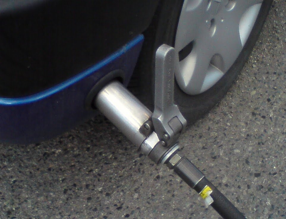
Summary in Norwegian: Hvorfor bygger ikke flere om sin bil til LPG? Det er overskudd på LPG gass, mesteparten bare brennes opp ute på oljeplatformen. Da er det bedre å brenne den opp gjennom motoren på din bil. Mange klimatiltak er direkte lønnsomme. Ombygging til LPG drift av din bil er et slikt tiltak. Driften har vært helt uproblematisk, selv uten årlige servicer på LPG anlegget. Der jeg fyller LPG gass opplyser de at LPG gassen i Norge er meget ren, og at det ikke er behov for årlig bytte av filter hvis man kjører lite. Bilde viser hvordan man kobler seg til LPG tanking i Norge.

Tuesday, March 2, 2010

Using PLX KIWI MPG to reduse fuel consumption

I bought a KIWI MPG trip calculator to be able to measure the fuel consumption in my Citroen Berlingo 2004. My hope was that it would help me learn how to drive the most fuel efficient, and I will give it credit for teaching me a few things. It does, however, have some bugs. Here is my short test and review.

It all started out after reading the tips on Ecomodder.com. Reading, understanding and then following these tips will most likely have the biggest impact on saving you fuel. But I like statistics and to compete with myself using the least fuel. That is why I bought the KIWI MPG.


I plugged the unit into the OBDII port in my car. The KIWI MPG indicated that my car had a "CALP" sensor, which is the one that needs to be calibrated. After some days of driving, I changed the 1.00 value to 0.27 to get fuel consumption close to actual use. Then I have tested it for several months.

It is interesting to see the fuel consumption when driving. Sometimes a try to push the clutch pedal to the floor and just coast, and then compare it to having the enging engaged and running. But can the display be trusted? When going downhill with the gear engaged and no throttle, I have been told that the car should be using no fuel. The KIWI MPG should be showing 0, but it is showing something like 2.4 (liter/100km). Another bug is that the unit does not always start when starting the car. Perhaps as often as 1 out of 3 times it does not start. Then I have to use the on/off switch. When I stop the car, the KIWI MPG does not always stop. It thinks the car is running and the average fuel consumption keeps rising, which ruins the average function. Twice it has gotten some kind of hick-up, showing much too low fuel consumption. Turning it on-off-on brings it back.

The best I can say is that it is an educational toy. After all it is fun, and I have managed to lower my fuel consumption with 5-10% after using it, or is it just because I am using the techniques from ecomodder.com ?

Update: This winter I was not using my car for a week, and after that I could not start it. Flat battery. Then I recalled how I had noticed one morning that the entire windscreen had been covered by a thin layer of ice, except for one small spot. This spot was about a foot above the location of the KIWI MPG. You can feel that the unit is warm even when it is in standby. I have now disconnected the unit, and have had no problems starting the car later this freezing cold winter in Norway. So make sure you unplug this unit if you are not going to use your car for a week or so.

Summary in Norwegian: Har din bil ikke en forbruksmåler? KIWI MPG er en bensinmåler du kan ettermontere i de fleste biler. Imidlertid er jeg noe usikker på hvor godt den egentlig måler forbruket. Det er en morsom dings. Kan kappe kjøre med meg selv til jobben for å se om jeg kan forbedre forbruket fra dagen før. Men jeg er ganske sikker på at det er teknikkene fra ecomodder.com som er det som virkelig monner. Enheten bruker mye strøm i standby, så den bør frakobles hvis du parkere bilen over lenger tid.